PLATTLINE ZINC RIBBON ANODES
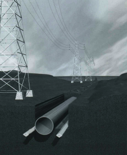
 The long-term trend in the United States and many other countries is shared land use for pipelines and other utilities. This movement has increased the number of overhead high voltage transmission lines parallel to and sharing a corridor with an underground pipeline. This combination has increased the need for grounding of the pipeline to dissipate interference.
In these systems, A.c. voltages are transmitted to the pipeline by conductive or inductive interference. Magnetic induction acts along the pipeline or pipeline segment that is approximately parallel to the power line and can cause significant pipeline potentials’even at relatively large separation distances.
Consideration must be given to safety of personnel and the public who may come into contact with above ground portions
of the pipeline such as valves and test stations. These exposed structures can be a potential shock hazard when touched while the soil is at a significantly different potential.
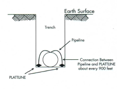
Advances in interference control have resulted in the gradient control wire method. This method consists of one or more bare zinc conductors buried parallel to and near the pipeline and regularly connected to it. Plattline™ zinc ribbon anode used in this way is very effective in mitigating excessive pipeline potentials due to both inductive and conductive interference. (See Figures I & 2.) Plattline evens out pipeline and soil potential differences. Additionally, Plattline can provide cathodic protection to the pipeline.
It is important to review the use and design of a gradient control wire system with an engineer experienced with this system, as its performance will depend on the multilayered structure of the earth.
For inductive interference, gradient control wires provide additional grounding for the pipeline and decrease the induced pipe potential rise. At the same time, they raise local ground potentials, thus sharply reducing touch potentials and coating stress voltages.
For conductive interference, gradient control wires dampen the soil potential rise close to the pipe while raising pipe potentials, thus providing reduced touch voltages and decreasing coating stress voltages.
Figure 2: Plattline connections to the pipe

FOR AC MITIGATION
Plattline can provide a significant means to mitigate potential gradients along the length of a pipeline. Importance must also
be placed on reducing the potentials at valve sites, metering stations, pig launchers and receivers and other accessible installations for worker safety.
Gradient control grids or grounding mats raise local ground potentials in the same way gradient control wires do. These
grounding mats can be made in several forms. Spiral and rectangular designs are generally standard for grounding mats. These are shown in Figures 3, 4 and 5. The most common size of Plattline for grounding mats is standard.
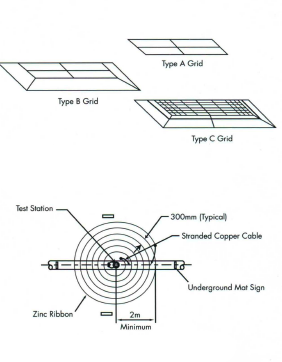
Figure 3: Rectanglar control mat examples
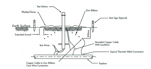
Figure 4: Spiral gradient control mat ( top view )
Reference should be made to NACE Standard RPO 177 (Latest Revision) – Recommended Practice on Mitigation of Alternating Current & Lightning Effects on Metallic Structure and Corrosion Control Systems. Also, ANSI/IEEE Standard 80 specifies safety design criteria for determining maximum acceptable touch and step voltages during fault conditions.
Finally, during fault conditions on the power line, the system must ensure that pipeline coating stress voltages remain within acceptable limits to prevent coating damage and damage to the pipeline steel. Coating damage can occur in the range of 1000 – 2000 volts for bitumen based coatings and in the range of 3000 – 5000 volts for polyethylene or fusion-bonded epoxy coated pipelines
Figure 5: Spiral gradient control mat side view
| Product Size | Super | Plus | Standard | Small |
| Cross Section Inches Millimeters |
1″ x 1-114″
25.4 x 31.75 |
5/8 x 7/8″
15.88 x 22.22 |
1/2″ x 9/16″
12.7 x 14.28 |
11/32″ x 13/32″
8.73 x 10.32 |
| Weight/Foot, Pounds Weight/Kg., Meters | 2.4
3.570 |
1.2 1.785
|
0.6 .8925
|
0.25
.372 |
| Diameter of wire core Inches Millimeters |
0.185
4.70 |
0.135
3.43 |
0.130
3.30 |
0.115
2.92 |
| Standard Coil Length Feet Meters |
100
30.5 |
200
61 |
500
152 |
12
30.5 |
| Standard Coil LD.
Inches Centimeters |
36
91.44 |
36
91.44 |
12
30.5 |
12
30.5 |
| Packaging | Steel-banded
random-wound open coils |
Steel-banded
random-wound open coils |
Wood Reels | Wood
Reels |