Typical Application:
•Above ground storage tank bottoms, pipelines, marine structures
Featuring:
•Design flexibility – modular design permits multitude of anode configurations
•Rapid installation – no field splices or weldments
•Light weight – very easy to ship and handle
Design Compatability:
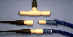
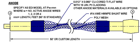
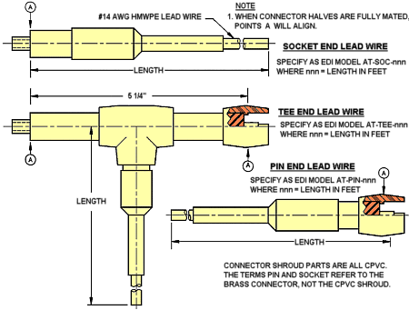
The Model AT is an impressed current linear anode system which permits maximum design flexibility. It consists of a copper cored titanium flat wire coated with platinum or mixed metal oxide and attached to a #14 AWG HMW/PE insulated bus wire. The wire pair is surrounded by a flexible plastic mesh. Individual anodes are 50 ft. long and are easily connected in the field to form a hermetically sealed joint. This allows the design engineer to choose a layout which is best suited for the application. Perhaps the most significant feature of the Model AT is its unique connector system. Each anode is supplied with a pin connector on one end and a socket connector on the opposite end which can be mated either to another anode section to form a string or to a power feed cable. Specially developed “tee” connectors allow intermediate current feeds on long strings. These connectors are designed for underwater cable connections and are being used successfully on other EDI products in turbulent aqueous solutions. All connections are factory made and sealed which means that there are no splices or weldments required in the field. Installation can be completed in substantially less time than any other system. For example, it takes less than 6 man-hr. to install this anode system in a 60 ft diameter tank.
AT Anode Assembly
| Pin and socket are brass Alloy 360 | Connector body is Neoprene |
| Power rating = 15 Amps | Insulation rating = 750V |
| Min. insulation thickness = 0.040″ | Contact resistance < 0.01 ohm |
| Insulation resistance > 200 megohm after wet mating | Pressure rating = 20 kpsi |
| Rated for 500 wet matings |
| 1. When connector halves are fully mated, points “A” will align. |
| 2. Current output not to exceed 10 mA/ft/wire. Use multiple wire anodes for higher current output. |
| 3. Individual anodes may be interconnected to form strings of any desired length. Power feeds must be no more than 1,000 feet apart on single wire anodes. |
| 4. Current should be fed into anode strings from both ends. Longer strings should have additional intermediate feeds. |
| 5. Assemble individual anodes into strings by pressing pin end fully into socket end. The joint and be made permanent by using any solvent cement suitable for use with CPVC. |
AT Anode Power Feeds
AT Anode Branch and End Plugs
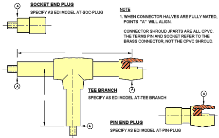
Tee branches and end plugs are used to make short side branches in a linear anode arrray. Use an end lead wire rather than an end plug to increase circuit redundancy
Undertank Anode installation
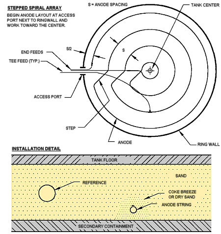
Anodes can be interconnected to form either one continuous string or several discrete strings. Lead wires are to be connected to both ends of anode strings. The Tee End Lead Wire is used to provide intermediate power feeds. Distance between power feeds must not exceed 1,000 feet on single wire anodes.
To ensure optimum anode performance, anode should be covered with calcined petroleum coke or fine dry sand. Make sure the material filters through the poly mesh and completely encapsulates the anode.